

1. Safety Precautions
IMPORTANT SAFETY INSTRUCTIONS
- Installation should be performed by qualified personnel only
- Disconnect all power sources before installation
- Follow all local electrical codes and regulations
- Ensure proper grounding according to local regulations
- Protect the device from moisture and extreme temperatures
2. Package Contents
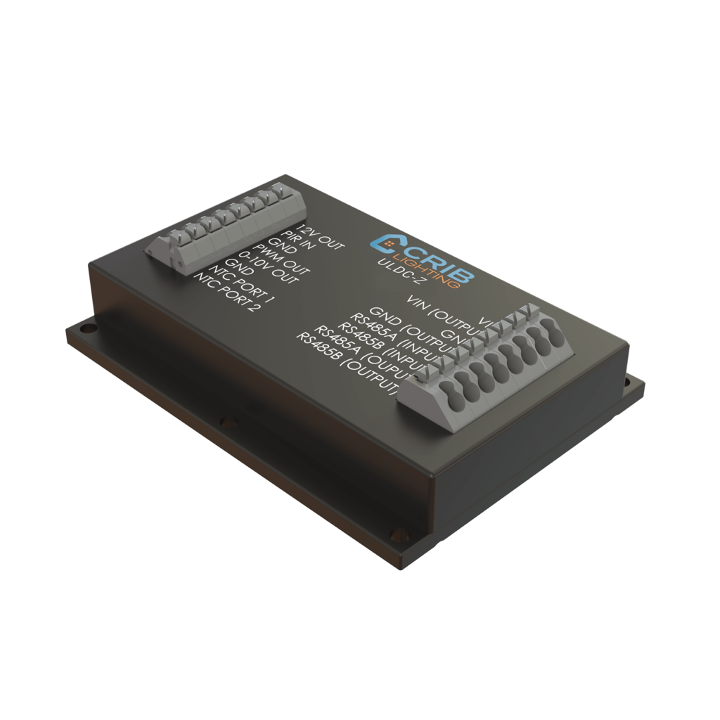
- ULDC-Z Controller
- Quick Start Guide
- Terminal connectors (2x 8-pin)
- Mounting hardware
3. Mounting Instructions
3.1 Location Selection
- Install in a dry, indoor location
- Ensure adequate ventilation
- Avoid exposure to direct sunlight
- Keep away from heat sources
- Allow minimum 50mm clearance on all sides
3.2 Mounting Options
- DIN Rail Mounting:
- Clip the upper DIN rail groove onto the rail
- Press the lower part until it snaps into place
- Verify secure mounting
- Surface Mounting:
- Use the four mounting holes
- Mark hole positions using the device as template
- Use appropriate screws for the mounting surface
4. Wiring Instructions
4.1 Power Connection
- Connect DC power supply (9-36V):
- Positive (+) to VIN terminal
- Negative (-) to GND terminal
- Observe proper polarity
- Use 18-24 AWG wire
4.2 0-10V Output Connection
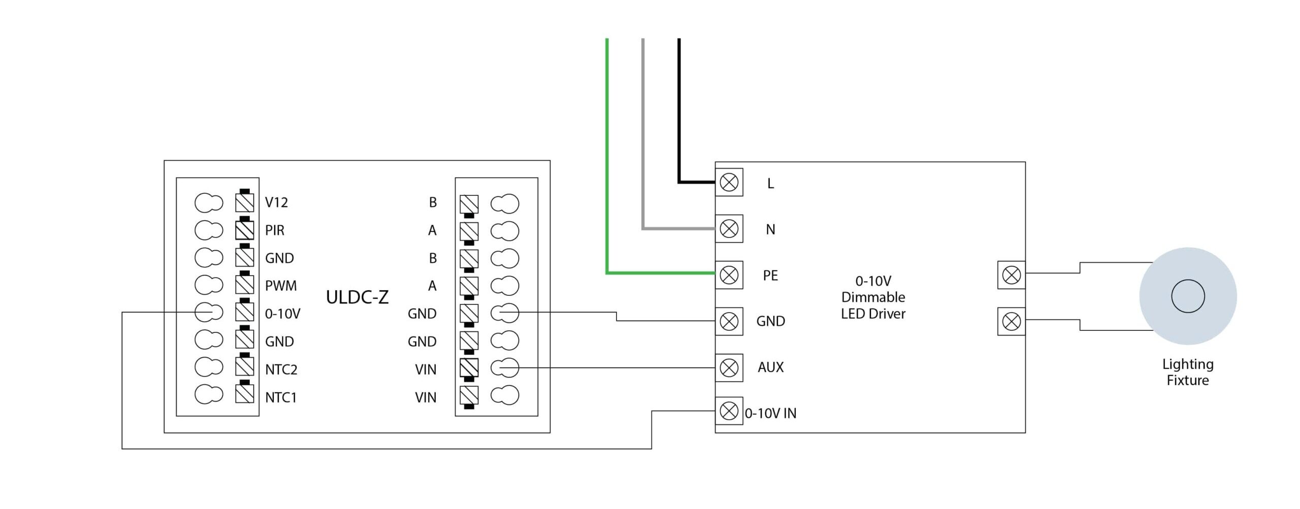
- Connect to LED driver:
- 0-10V(+) terminal to 0-10V IN terminal
- GND (-) terminal to GND terminal
- Maximum 20mA sink current
4.3 RS-485 Connection (optional)

- Connect RS-485 network:
- A (+) to RS485_P terminal
- B (-) to RS485_N terminal
- Use twisted pair cable with shield
- Enable termination resistor if end of line
4.4 Temperature Sensor Connection (optional)
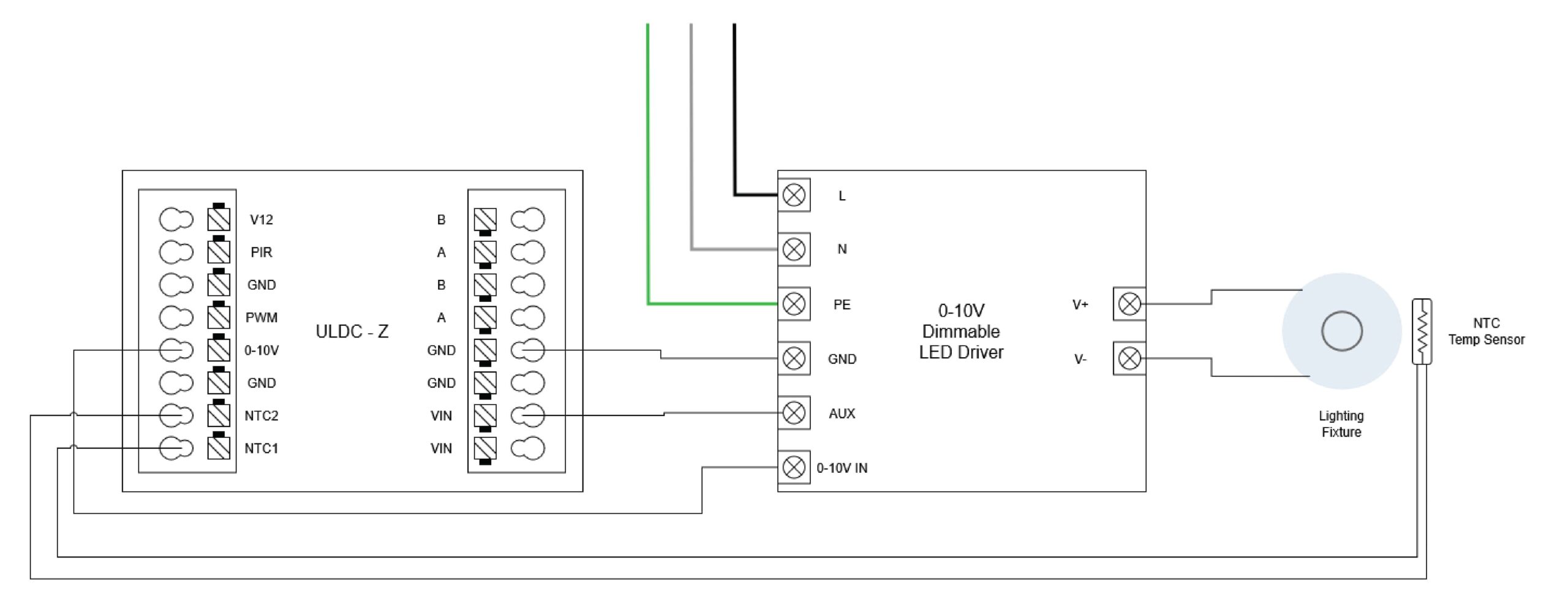
- Connect NTC sensor:
- Connect to NTC-1 and NTC-2 terminals
- No polarity requirement
- Use twisted pair cable for lengths >30cm
- Shield recommended for noisy environments
4.5 PIR Sensor Connection
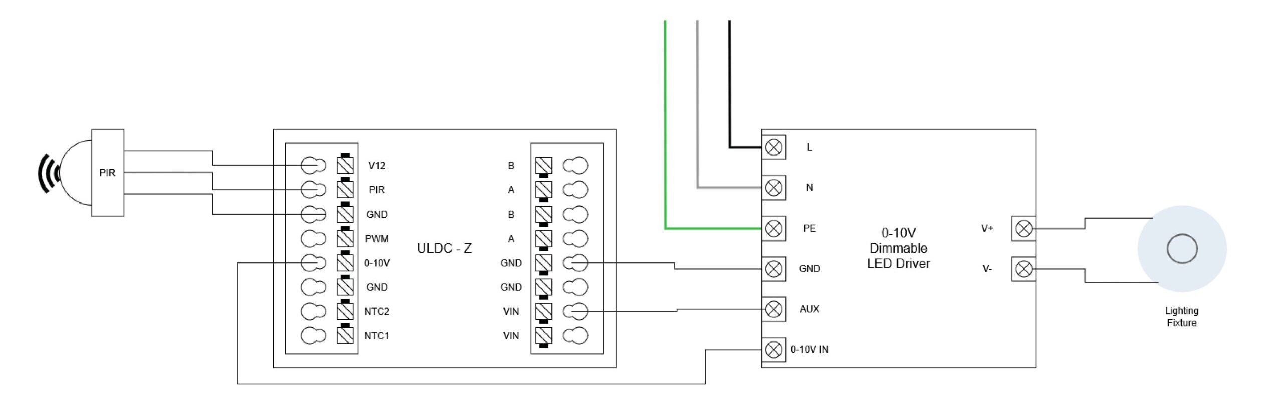
- Connect motion sensor:
- Connect to PIR_INPUT terminal, 12V terminal and GND terminal
- Observe sensor voltage requirements
- Use shielded cable for lengths >2m
5. Configuration and Setup
5.1 Initial Power-Up
- Verify all connections
- Apply power to the unit
- Check status LED indicators:
- Power LED solid
- Status LED blinking
5.2 Network Configuration
- For wireless setup:
- Use CRIB app (available separately)
- Follow in-app instructions for device pairing
- Configure network parameters as needed
- For RS-485 setup:
- Set communication parameters on app
- Configure protocol (DMX/Modbus)
- Enable termination if required
6. Troubleshooting
6.1 Common Issues
- No 0-10V output:
- Verify wiring polarity
- Check LED driver compatibility
- Verify configuration settings
- Communication issues:
- Check cable connections
- Verify network settings
- Check termination settings
- Temperature sensing issues:
- Verify NTC connections
- Check sensor specifications
- Validate temperature readings
7. Maintenance
- Regular inspection of connections
- Clean cooling vents if present
- Check mounting security periodically
- Update firmware when available
- Document any system changes